A Moebius Building for CS
This is a study of the design process
carried out in the context of a pair of courses:
a CAD-oriented design studio taught by Yehuda Kalay,
and a CS graduate course on architectural CAD taught by Carlo H. Sequin
during Spring 1995.
The Task and the Given Constraints:
Function
Design a new building for the CS Division using the Program for
Soda Hall as completed in 1994.
This implies a building with a gross square footage of not more
than 100,000 sf (campus imposed limit),
and with at least 60,000 assignable square footage (client demand).
The detailed specification
on the number and sizes of the various spaces
must be observed rather closely.
These constraints seem to call for a design approach
traditionally known as "Form Follows Function".
Form
Because of the mathematical orientation of the client,
the building must be in the shape of a Moebius band.
The inspiration for this "outrageous" specification comes
from a proposed design for a Moebius building by Eisenman.
This yields a design task in which FORM will appear
as a very strong design constraint which might imply
the design theories known as "Function Follows Form".
Context
The building must be designed for a site located immediately
to the west of Evans Hall, overlooking the glade to the north of
Doe Library.
It appears desirable that the new building covers and detracts
from the stark concrete facade which is visible
from all the way across the San Francisco Bay.
Design Philosophy
I view design as a constrained optimization process
in which function, form, and context may all appear as constraints
to the degree that are specified originally.
At the same time, functionality (usability), shape (beauty)
should be maximized, while simultaneously cost ($$) and
negative impact on the environment (context) should be minimized.
Initial Design Space Exploration
It appears that the constraint on the shape of the building
is the most difficult constraint to meet,
so we first explore what it means to design a building
in the shape of a Moebius band.
The design by Eisenman, shown below,
does not provide much insight.
It is also not clear how this form can be made usable
to a client who wants a couple of hundred nice cubicle offices
that efficiently accommodate rectangular Steelcase furniture.

The Moebius Property
Geometrically, a Moebius band is an infinitely thin,
single-sided surface with a single contour.
Most often it is represented by a belt with a half twist.
The key feature is that when we scoot along the surface of the belt,
we will have to make two loops around the length of the belt
in order to come back to the same position from where we started;
furthermore, half-way through this path, we visited the spot
on the opposite side of the belt surface.
For architectural purposes we are not interested
in a thin mathematical surface, but we want a building structure
with some volume, so we need to consider prismatic structures
of substantial thickness with some built-in twist.
For our initial analysis, we thus give the band a rectangular
cross section and we look for single right-angled shapes
that conserve the essence of a Moebius strip.
Thus if we follow along a face of that prismatic ring,
we expect to have to make more than one loop around the ring
before we came back to the starting point, and in that process
we expect to visit "other" faces of the prismatic structure.
Such a structure can be built for a four-sided prismatic structure
with a suitable assembly of only 10 unit cubes, as shown below.
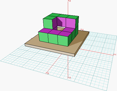
Three cubes in sequence form either a straight row or a small symmetrical
L-shape. Four cubes in sequence can also form an asymmetrical L-shape with one
leg twice as long as the other, or a planar "Z"/"S" jog structure, as well as a
twisted Z-structure which may appear as a right-handed or as a left-handed
version. It is the appearance of this twist element that basically carries a
path on the surface of the prismatic structure from "one face" to "another".
In the simplest case shown above, there is really only a single connected
prism face. Since there is a single occurrence of the twisted Z, our path makes
a twist of 90 degrees on every loop around the structure. It thus takes four
loops to come back to the starting point, and during this traversal we will have
visited all the exposed cube faces on the whole structure. Thus, a building in
this particular shape could basically qualify to be a Moebius band if the client
is willing to accept such a broad interpretation.
But let's assume that the client wants a "normal" Moebius band,
in which we return to the starting point after only two revolutions.
In this case, we have to introduce two twist elements into the loop,
so that the total prismatic twist around the loop becomes 180 degrees.
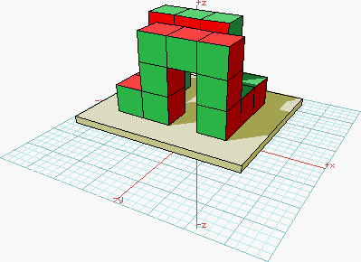
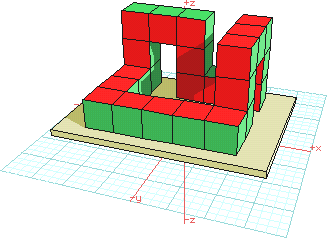
There are several basic configurations;
the twist elements could be in adjacent or in opposite corners of a square loop,
with the ribbon returning to the ground plane after each twist element,
so that the two 90-degrees twist add rather than subtract.
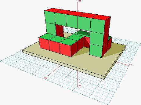
 Alternatively, we could use an upwards path section as well as a downward
section to form a twist element, but then we need to continue the
horixontal path in the opposite direction from the original one.
The path needs then be closed with either an S-shape through the middle
of the vertical loop, as shown below, or with a spiral section
around the outside of one of the vertical pillars.
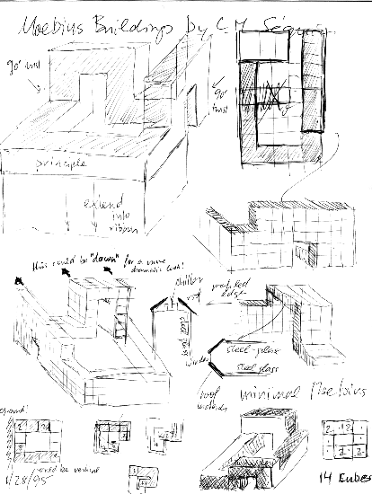
Below are some of the sketches I did in trying to understand the essence
of a Moebius band for building design and the architectural possibilities
to demonstrate such a shape clearly, while still maintaining a shape
that is usable in a traditional way.
Architectural Enhancements
Here are some thoughts on how to enhance the basic shape
with architectural features.
To give the building more of a "belt shape" where the "surface" faces
are clearly distinguishable from the "edge" faces
in our prismatic structure, we will make the cross section
of the prism rectangular with a substantial aspec ratio,
say at least 3:1. To further enhance the visual distinction between
the two types of surfaces, one could make them of different materials,
for instance, the wider surface could be made from a combination of steel
and glass, and the narrower prism faces could be formed in concrete.
The figure below shows a possible basic structure using such a 3:1 prism.
In this figure we have put the two twist corners next to one another
to minimize the length of the portion where the belt rectangle
lies horizontal and where the steel/glass surfaces would have to cover
the top and bottom of the building section.
Alternatively, if the two types of surface treatments are about
equally suited for the treatment of vertical and for horizontal surfaces,
the two twist corners could again be placed at diagonally opposite
positions, which would result in roughly equal portions of the building
with a horizontal and with a vertical cross section.
To make a single, "more visible" edge that one can follow with the eye
and convince oneself that there is indeed just one such edge and not two,
we can enhance the small side of rectangle with some structure
to yield a visibly prominent edge.
Perhaps a wedge added to that face would do it.
The wedge could be treated somewhat differently
depending in what orientation it appears.
As a first solution we might try to keep indeed a sharp edge
at the apex of this wedge all around the building loop.
Where the wedge runs at the side of the building,
we might want to still have some windows in it;
but for consistency we might then also want windows where
the wedge forms an actual roof.
Perhaps some differences in window treatment is permissible,
and we might then have some mansardes on the roof portions
and some different type of small bay windows
sticking out from vertical wedge facades.
Alternatively we might want to split the wedge,
and represent the single edge as a large "crease" or gap.
When it is on top, the wedge would take the form of a gabeled roof,
split into two halves with a space in between for air-handling units
and other equipment that one typically finds on the roofs
of large office buildings or in special louvered "penthouses".
When the wedge runs on a vertical face, the gap could be used
to place some recessed windows in it; these windows might be sufficient
for staircases or for the ends of corridors.
Considering the Context
The shapes designed above demonstrate the geometry of a Moebius band,
but the lead to ring shaped structures that cover more ground
than we have available in the dsignated site,
and they do not seem to do much to "cover up" a major portion
of the west facade of Evans Hall.
Thus we need to look for a more vertical implementation of
this Moebius building.
Here are some sketches made with the goal to solve this problem:
A promising looking structure with a large dominant vertical arch
which should be capable of covering a lot of the Evans facade
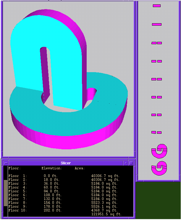
was entered textually in UniGrafix form and was then processed by the
slicer tool.
This gives us some quantitative information on floor spaces
and on overall size.
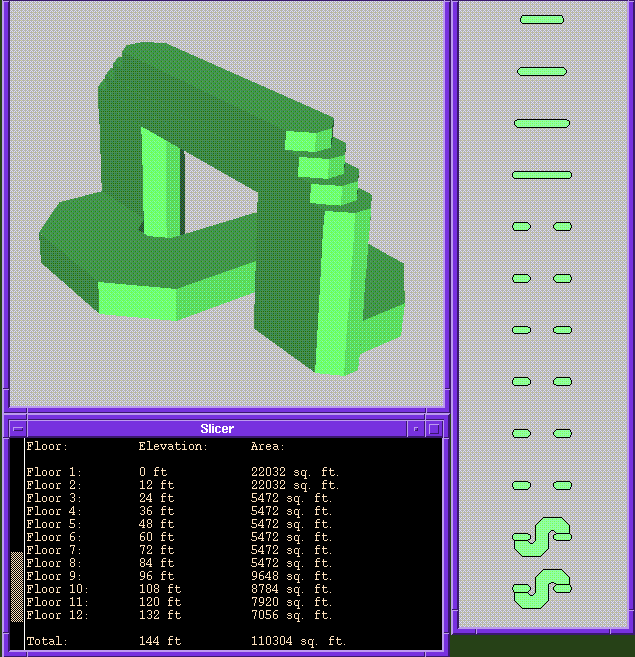
As we can see, the building is somewhat too big.
This could be remedied by taking out one floor level
in the two vertical pillars.
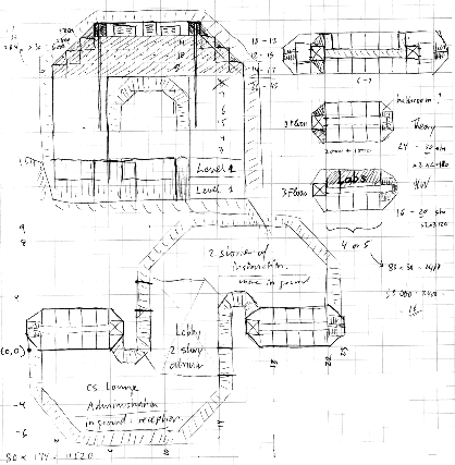
I then started to look at the internal structure of the building
and at the generic floor layouts.
The ribbon forming the loop of the building has the thickness
of two office lengths (15'+15') plus one corridor width (6').
The width of the ribbon is chosen to accommodate about 5-6 offices
on a side and to yield an aspect ratio for the ribbon of at least 2:1.
The elevators run on the inside edges of the pillars
so that they can reach all the way to the top of the loop.
The fire stairs will be placed at the outer edges in the loop.
I found it rather difficult to fit stairs into the wedge-shape edge
of the building, since I needed large enough landings at the
end of the central corridors on each floor.
It also occurred to me that the fire marshall may insist on having
at least two stairs serving every floor portion in the pillars.
This would lead to some inefficiency of floor utilization
which might make it difficult to accommodate the 60% utilization rate
specified by the client.
Another problem is that the large bridge forming the upper part
of the loop may lead to rather high construction costs.
Revised Massing Study
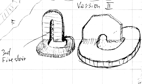
Thus I tried an alternative approach where I make the loop much narrower
and put one shared central fire exit stairs in the middle
between the two pillars.
I plan to make this an external, very light-weight, almost transparent
metal construction, and hope that since it is on the "outside" of
the actual building shell, it will not be counted towards the
gross square footage of the building,
thus giving me a larger fraction of the floor spaces to provide
assignable room functions.
The narrower loop and the asymmetrical lobby
also seem to make a more interesting architectural statement.
Here is the basic concept:
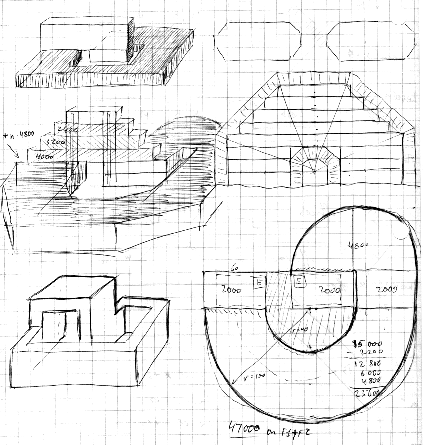
I tried some variations on the concept to determine the range
of the size of the building and various ways to implement
the vertical loop and the horizontal spiral:
And here is the chosen shape analyzed with the slicer tool.
This time I tried to stay with a simple rectangular cross section
for the ribbon, to keep the loops as narrow as possible
and to avoid the potentially hard-to-use space at the "edges"
of the ribbon.
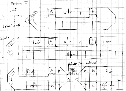
Here are some conceptual floor layouts:

The problem with this design is that it has too much of its massing
in the base which cannot be made much smaller.
To try to overcome this and to make the vertical structure more dramatic
in a 3-dimensional sense, I tried to put the two pillars at right angles
and to make the top curve follow a cone shape
(roughly pointing at the path of the sun).
This also reduces the size of the base.

This obviously presents some construction problems
for the floors in the cone section.
Also it is difficult to accommodate elevators
that go all the way to the top floor.
Thus here is a more angular variant:
<
Surface Treatments
The big flat side of the vertical loop will house many offices
that would like to have relatively large windows and good views.
So there should be a fair amount of glass on that facade.
If we want to have a smooth round loop on the top,
behind which we will have again 3-4 floors of offices,
we need to make this facade relatively unstructured,
since the offices will maintain a fixed horizontal position,
thus the external look of the window cannot reflect
the internal active portion.
In the vertical loop, the narrow side of the ribbon,
will either hide elevators or fire stairs
and on the top turn into a "roof" over the air-handling units.
On the lobby floors closing the ribbon along the ground,
the narrow edges are the main window fronts,
and the wide glass walls of the vertical loop
transition into the roof of this section.
Picking materials that are distinct enough to make the form
of the Moebius band clearly visible yet serve the different functions
in the different parts of the building will be quite a challenge.
Matching Form and Function
So far we seem to have found a realizable way to deal with the
specification that the building take on the basic shape of a Moebius band.
The next step is to match up the functional elements specified by the client,
in particular the offices, with the overall structure
in a practical and harmonious way.
Here we can use some other tools developed in CS294-5:
the Bubble Diagram Builder (BDB), and the Floor Space Manager (FSM).
We read in the room specifications into the BDB
and then regroup the given functions to make clusters
of 5 faculty offices, a visitor office and a couple of
administrative support offices.
These we try to allocate to the top floors with the FSM.
Next we formed some student office clusters and accommodate them
in the pillar sections of the building.
In some of the pillar sections we will also place the research labs
close to the respective student office clusters.
One pillar may have most of these labs stacked vertically
on the back side towards Evans,
while the other pillar will be mostly offices,
accommodating the theory and software groups.
In the latter floor sections we may place instead some
discussion lounges or seminar rooms.
On the two lobby floors, we accommodate all the instructional
and administrative functions.


