Wireless Embedded Internetworking Short Course
David E. Culler
Department of Electrical Engineering and Computer Science
|
|
Lab 7 Sensing |
|
In lecture we went through the theory and practice of transducers, which convert a physical phenomenon into a voltage, and ADCs, which covert that analog voltage into a digital value. The final step, of course, is to convert that digital value into meaningful engineering units for the original phenomenon, e.g., degrees for temperature, g’s for acceleration, volts for electric potential, amps for current, lux for light, % relative for humidity and so on.
Some sensors simply generate a voltage, which is then digitized. Others change the electrical characteristics of some material, i.e., its resistance or its capacitance. By putting a current through the material, we end up with a voltage that we can measure.
Resistive Sensors
One important class of range-valued sensors is resistive sensors, which includes thermistors, proto-resistors, strain gauges, flex strips, and some thermocouples. Electrically, these devices are passive circuit elements with a variable resistance that changes in response to physical conditions. For example, Figure 1 shows how the resistance of a particular thermistor (Panasonic ERTJ 4500K) decreases with increasing temperature. At 0 °C, it has a resistance of 18 MΩ, at 25 °C it obtains its rated value of 4500 KΩ, whereas at 100 °C it has 220 KΩ. The datasheets for the particular sensor give the conversion functions in detail. To obtain the reading in physical units, we must observe the resistance and then compute the corresponding temperature, or whatever physical phenomenon is being sensed.
Figure 1 Characteristic Function of a Thermistor showing Resistance as a function of Temperature
While a switch has either infinite resistance (open) or zero resistance (closed) these devices take on a range of resistances in between. By placing them in a voltage divider circuit, as illustrated in Figure 2, this variation in resistance is converted into variation in voltage, which can be measured by an ADC to get a digital reading for voltages between zero (V=GND) and Dmax (V = Vref) .
Figure 2 Conversion of a Resistive Sensor to an Analog Voltage to a Digital Value
The voltage, VA, at point A in Figure 2 is equal to
VA = Vacc * Rsensor / (Rsensor
+ Rcomp),
where Vacc is the analog supply voltage, Rcomp is the resistance of the pull-up, and Rsensor is the effective resistance of the sensor.
This analog input, VA,is sampled by the ADC in the microcontroller and compared to a reference voltage, Vref, to produce a digital value D between zero and Dmax such that
D = min(Dmax , Dmax * VA / Vref ).
A 12-bit ADC is provided by the TI MSP microcontroller, so Dmax = 4095 (or 0xFFF). The reference voltage, Vref, can be set to 1.5 V, 2.5 V, or Vcc.
In many situations a constant, regulated voltage is most useful as a reference. However, for simple resistive sensors it is convenient to have the reference voltage be the same as the supply voltage to the sensor, Vref = Vacc = Vvcc, even when this is an unregulated battery voltage. This configuration is called a ratiometric sensor; all we need to determine the physical condition being sensed is the ratio of the resistances. For example, when Rsensor = Rcomp, we will get a reading of D = Dmax / 2, independent of the supply voltage. Using the lookup function from the sensor datasheet, we can convert this to physical units.
In general, for a ratiometric sensor we will get a reading of
D = Dmax * Rsensor / (Rsensor + Rcomp).
Solving for Rsensor we get
Rsensor = Rcomp * ρ / (1- ρ), where ρ = D/ Dmax.
In practice, with a ratiometric sensor, you cannot use the full range of the ADC, because the output voltage will be significantly less than the reference voltage. If a small Rcomp were used so that the output voltage would be close to the reference when the sensor resistance is large, then at the other range of the scale both resistances would be small and too much current would be drawn through the voltage divider. If Rcomp is chosen to be roughly equal to the effective sensor resistance at the high end its useful operating regime, half of the ADC range is used. (The most significant bit will be zero.) A smaller Rcomp can be used, increasing the range of readings, as long as the current does not exceed the microcontroller tolerances and power consumption fits within the application power budget.
Alternatively, if a fixed voltage reference is used for the ADC, we can determine VA from the observed input D as
VA = Vref * D / Dmax,
as long as VA < Vref. Vref will typically be smaller than the supply Vacc, so in this case, the value of Rcomp should chosen be so that at the end of the desired sensing range with the largest resistance, VA ≤ Vref.
The effective resistance of the sensor is calculated as
Rsensor = Rcomp * α / (1 – α), where α = VA / Vacc.
Our thermistor example raises a useful tidbit. Although thermistors are resistors that are designed specifically to vary their resistance with temperature, in practice all resistors are temperature dependent to some degree. In fact, many different kinds of sensors exhibit some temperature dependency. The datasheets will describe how to do the temperature compensation in the conversion to physical units. Some sensors will provide built-in temperature compensation – especially high quality digital sensors. In many real applications, the data analysis will utilize multiple sensor nodes to gain high quality physical information.
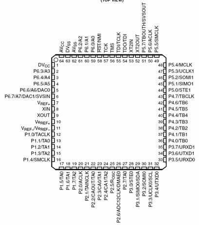
The Epic interface board exposes the external ADC channels as pins adjacent to the Epic core module. The eight external ADC channels are the special functions for the pins on port 6. There are also internal ADC channels for measure Vcc and the internal temperature. The roles of the pins and ports is indicated in the pin out diagram below.
The behavior of the Msp430 ADC is described in chapter 17. We’ll describe it in terms of the code below.
The epic interface board provide 3-wire connectors for four of the ADC channels. We brought along several sensors that attach directly to these connectors. You can do a lot of configuration of the signal conditioning with simple jumpers on the board. A schematic for one input is shown below. For ratiometric sensors a jumper can be used to select any combination of the three pull up resistors. The voltage supply to the sensor can be selected to be either Vcc or an output pin on Port 5. The latter is used for low power operation when you only want to power the sensor during sampling.
Voltage Source Sensors
Another important class of sensors is those that are essentially voltage sources. Consider for a moment a generator – when the armature spins it generates current. Tachometers, speedometers, anemometers (wind speed meter), and many other devices are similar. The sensor need not have moving parts to be a voltage source; it may have its own independent source of power. In any case, it becomes an active element in the circuit.
The main complication that arises in this case is when the maximum useful output voltage does not match well enough with the available references on the MSP. Some external sensors have very small voltage swings – millivolts in various cases. In this case, operational amplifiers and other signal condition is used to match to the reference.
In some cases, the output voltage is higher than the available ADC reference voltages, say 5V or 12V so a level conversion is required.
General Analog Sensors
With the thousands of different kinds of sensors that exist and the many interfaces, no fixed set of interfaces can cover them all without external circuitry. For example, many moisture sensor, humidity sensors, and touch sensors are capacitive, rather than resistive. The changing physical conditions change the capacitance of the device. Additional circuitry transforms this change into a change in voltage, which can be measured with the ADC. Many industrial sensors use “current loops” with 4-20 mA signaling where the sensor modulates the flow of current, rather than the resistance or the voltage. Putting a variable current across a fixed resistor creates a variable voltage, which can be provided to an ADC. These kinds of devices often require a specific excitation voltage, they use various signaling voltages, and some provide differential outputs. External signal conditioning circuit should adapt these inputs to a form similar to voltage-source sensors, described above. These sensors can be connected to the Extender as in Figure 9 or Figure 10, as appropriate, through additional circuitry on an external board or on the prototyping area. Typically, they will require a separate voltage supply. Additional IO ports may be used to configure or control these devices.
General Digital Sensors
Increasingly, many sensors incorporate the analog-to-digital conversion internally or directly produce a digital output. These have a range of interfaces, mostly serial, including RS232, UART, I2C, SPI, and 1-wire. The internal humidity and temperature sensor on the Primer Pack nodes are such digital sensor, using I2C.
ADC Drivers
ADC drivers are complex enough that rather than build one up like we did for digital inputs, let’s start with a reasonably good solution. The Msp430ADC12 component is a reasonably good, yet simple ADC driver. The standard TinyOS distribution has very sophisticated ADC drivers with built-in arbitrators for shared resources. That level of generality is helpful in trying to build hardware independent solutions. But it is hard to see how those subsystems really work. The one we have provided you is simple enough that we can walk through it easily.
The basic interface is associated with an individual ADC channel. It has commands to enable and disable the channel and to initiate a read. When the read is complete, it will signal ad readDone event. This is a classic split-phase design pattern that appears throughout tinyOS and tinyOS application. A command initiates action, typically by kicking some hardware resource into action, and completes. This allows the MCU to go to sleep if there is nothing else to do. Or it may service other events. The important thing is that is does not block, waiting for the operation to finish. Instead, an event is signaled upon completion.
interface Msp430Adc12 {
command void
enable( uint8_t refvolt );
command void
disable();
command error_t read();
event void readDone( uint16_t val, error_t error );
}
The enable command establishes the reference voltage for the acquisition.
As with the Msp430Ports driver, Msp430ADC12C is a configuration that provides a parameterized Msp430Adc12 interface for each of the channels. It is reproduced below. Notice that it has its own internal virtual time so that it can wait an appropriate length of time for the sample that it acquires to settle. It also uses the HplSignal to deliver the interrupt when acquisition is complete.
configuration Msp430Adc12C {
provides interface Msp430Adc12[ uint8_t channel ];
}
implementation {
components Msp430Adc12P;
Msp430Adc12 = Msp430Adc12P.Msp430Adc12;
components new TimerMilliC();
Msp430Adc12P.Timer -> TimerMilliC.Timer;
components KernelC;
Msp430Adc12P.HplSignalAdc12 -> KernelC.HplSignalAdc12;
}
Study the data acquisition logic in the Msp430Adc12P module referring to chapter 17 of the users guide for an explanation of the control registers and the individual flags.
Exercise
Modify your reporting
application to sample analog sensors.
You may want to use the internal voltage and temperature sensors, but it
is much more interesting to have external sensors. Pick some from the available set in
class and build a simple reporting application around them
Section 2. Conversion to
Engineering Units
So far we have been using
raw ADC counts. The engineering
unit of the phenomenon being measured is volts. What is the range of the measured values
(in engineering units)? What is the
accuracy of the measured value? How
do these compare to the range and precision of the ADC outputs?
How would you work with
the Vcc reading so that it outputs the measurements
in units of volts to a precision of 0.1 v.?
The obvious way to start
is to use FLOATs in the C code. Start there and notice how the code size
increases when the floating point libraries are included. (There is no hardware floating point. There almost never is on
microcontrollers. ) You will
discover that sprintf does
not handle %f. So you’ll need
to work around that.
Eliminate the use of
floating point by doing your calculations in fixed point. You may remember that one beauty of 2s complement
arithmetic is that it does not care where the binary point actually is. (The binary point is all in the eye of
the beholder.) Let’s use an
8.8 fixed point.
Modify your application to convert to volts in this fixed point format.