Wireless Embedded Internetworking Short Course
David E. Culler
Department of Electrical Engineering and Computer Science
|
|
Lab 3 - Programming TinyOS
|
|
TinyOS Concepts
As a part of this exercise, we’ll get a feel for how to program in the TinyOS component framework using the nesC programming language. TinyOS and nesC are designed specifically to address the unique issues presented by programming vast networks of low power devices that are embedded in the physical world
- Reliability – the real world is noisy and full of all sorts of unexpected variation. And with thousands of unattended devices in hard to reach locations, visibility and access are very limited. And these networks need to run for years. Software for this regime needs to be assembled carefully out of proven components. NesC provides linguistic support for the TinyOS component architecture. It allows software systems to be constructed like we construct hardware. We take tested components with well-defined interfaces and compose them into larger components.
- TinyOS systems are written in nesC using two kinds of components: modules, which implement functionality directly, and configurations, which wire together components to achieve a useful higher-level component. Lower level components abstract hardware modules. Higher level components provide application services. Components are more restrictive than objects in that they are instantiated at compile time and interconnected in a blueprint fashion. At the same time, they can be composed in ways that we would not consider with objects.
- Components are connected through interfaces. An interface consists of a collection of logically related command and event methods. Commands are implemented by the component that provides and interface and called by all components that use the interface on that particular component. Event handlers are implemented by components that use an interface and are signaled by the provider.
- Concurrency – embedded systems are fundamentally about handling events. Periodic sampling is driven by timer events. Alarms and alerts may be triggered by hardware that causes interrupts. Networking involves juggling a host of events at each level of the stack, physical hardware events, link protocol state transitions, networking protocol events, transport, and so on. NesC provides linguistic support for the TinyOS structured event-driven concurrency module. Modules contain tasks and handlers. Either can call command handlers in other components or signal event handlers. Handlers in a module may post tasks. There may be many concurrent tasks in a system. They execute atomically relative to other tasks according to a scheduler. Tasks may be pre-empted by low level asynchronous events. Typically, TinyOS systems provide a clear demarcation line between low-level “asynchronous” processing (i.e., interrupts) and synchronous concurrent processing. This boundary is crossed by posting a task, although tasks have many other uses. The TinyOS concurrency module is designed to enhance reliability, as well as to provide a clean way to handle extensive concurrency with limited storage.
- Protected Access to Limited Memory – storage on embedded systems is limited. It is THE limiting resource. In addition, concurrent activities interact through shared state. NesC provides linguistic support for the TinyOS storage model which eliminates global access to memory to enhance reliability.
- Modules contain storage in the form of local variables. The scope of that storage is the module. Tasks and handlers in a module can access that storage. Other modules must access it through an interface. The designer may choose to implement a “shared state” module, but even so access is mediated by the interface to the module. Efficiency of access to shared state is addressed by extensive compiler optimizations. Designers should be extremely careful about exposing internal state by passing pointers across an interface. This practice is used primarily for access to message buffers and to read-only properties.
- Tasks and handlers execute within a single stack. A general threads module requires that a distinct stack be allocated to each thread of depth sufficient to cover the deepest possible call chain. Such a programming module is not only space inefficient, it encourages the construction of arbitrary scheduling interrelationships mitigated by synchronization operations on shared variables and complex scheduling to enforce priorities and deadlines. TinyOS uses a consistent, structured event driven concurrency model. Simple schedulers suffice because the composition of components directs the concurrent interactions.
- Networking – networking is inherently asynchronous and event driven, requiring concurrent buffer management. Thus, most of the concepts in TinyOS are designed to support construction of networking abstractions and protocols. Networking also involves communicating between different machine. Different machines utilize different representations for numeric values and different layouts in memory. NesC provide machine-independent structures so that issues of “endianess” and the like can be handled by the compiler rather than decorating code with all sorts of error prone conversions. This encourages defining compile-time parsing of packet formats using structs.
- Specialization – embedded networks come in thousands of application specific forms. Rather than a “one size fits all” TinyOS provides rich tools for composing application specific systems out of generic building blocks. NesC provides generic components, both generic modules and generic configurations, and parameterized interfaces to make facilitate construction of finely tuned application specific solutions out of robust, yet flexible building blocks.
TinyOS Programming
We will first meet the core concepts of TinyOS programming in a simple example that senses a binary input and actuates a binary output, without any explicit networking. We are taking a “kernel approach” which is very different from how TinyOS was historically taught. When TinyOS was created it was designed to provide a framework for creating embedded network system abstractions and allowed the abstractions themselves emerge with time and experience. This more modern kernel approach reflects much of that consolidation. Such a kernel boundary could be established for any set of abstractions extending up from the hardware. In this case, the kernel provides the networking stack and the underlying implementation on the radio, microcontroller, and associated interconnection. And it utilizes a minimal set of MCU timer resources. It leaves exposed all of the
Please take a look at the files in $TOS/button/.
The overall embedded system is represented by BlinkC.nc, which is reproduced below. All nesC files have the .nc extension. The naming convention is that components that provide a useful abstraction are of the form xxxxC.nc whereas those that are auxiliary support for a useful abstraction are of the form xxxxP.nc. Interfaces are of the form xxxx.nc.
Let’s start with the core application component, BlinkP.nc, which is reproduced below. The BlinkP.nc component is a module, rather than a configuration. It implements basic functionality - receiving inputs and taking actions. The declaration section specifies all the interfaces that it uses and that it provides. (Here is provides none.) This module uses two distinct Led interfaces. Each has a specific role. The implementation section contains the storage, handlers, and tasks for the module. (Here there are no tasks and no commands.) It consists of three event handlers, each associated with an interface. The rest of the system provides the implementation of these interface. For example, it may bind interface to specific hardware resources, such as the LEDs on certain microcontroller pins. This module has one byte of storage, red. It is entirely private to the module.
module BlinkP {
uses interface Boot;
uses interface
Timer<TMilli>;
uses interface Led
as TimeLed;
uses interface Led
as ButtonLed;
uses interface
Button;
}
implementation {
uint8_t state = 0; /* Internal module state */
event void
Boot.booted() {
call
Timer.startPeriodic( 1024 ); /* start timer
at 1 sec*/
}
event void
Timer.fired() {
state = (state+1)
& 3; /* State LED on 1 of 4 seconds
*/
call
TimeLed.set((state == 3));
}
event void
Button.pressed() {
call
ButtonLed.set(!call ButtonLed.get());
}
}
The behavior of this module is straightforward. On boot, it starts a 1 Hz periodic timer. When the timer fires it advances the state, which behaves at a 2-bit counter. One quarter of the time it lights an LED. In addition, when a specific button is pressed it toggles an Led. While this is certainly a toy module, it illustrates regular sampling and control actions, as well as responding to alarms. It also illustrates several important TinyOS concepts. Notice the event driven execution model. Buttons are being pressed and timer events fire. They are services as they happen. It also shows the use of well defined interfaces.
Standard TinyOS-2.x interfaces are typically installed in /opt/tinyos-2.x/tos/interfaces/. This directory is included on the nesC search path as part of the $(MAKERULES). We have configured your VM to set of environment variables correctly for these Makefile rules.
One of the interfaces provided by the KernelC component is the Boot interface, which is described in detail by TinyOS Enhancement Protocol (TEP) 107 and specified by /opt/tinyos-2.x/tos/interfaces/Boot.nc. The interface is quite simple; it consists of a singled event, called booted, that is reproduced below.
interface Boot {
/**
* Signaled when the
system has booted successfully. Components can
* assume the system
has been initialized properly. Services may
* need to be
started to work, however.
*
* @see StdControl
* @see SplitConrol
* @see TEP 107:
Boot Sequence
*/
event void booted();
}
Once the kernel has booted successfully, it signals the booted event handler in each of the components that are wired to it so that they might initialize themselves. In essence, the BlinkP and ButtonP components register call-back with the kernel at compile time. We will look later at what these various components do with the booted signal. Signaling events is one important aspects of interfaces. Boot is rare in only containing events. Events are usually in response to some action that has been initiated by commands. Thus, interfaces are bi-directional containing commands and events.
The standard TinyOS distribution provides a rich interface for arrays of LEDs, which can be found in /opt/tinyos-2.x/tos/interfaces/Leds.nc. It has no events, only commands. We are going to start with a simpler interface for a single LED which can be found in ../drivers/Led.nc. This driver directory is included in the Makerules that we have put together for this short course. It treats the LED state as an attribute, albeit and active one. The value of the attribute is the state of the LED. Setting it to 1 turns it on; 0 turns it off.
interface Led {
command bool get();
command void set(
bool val );
}
Time is a fundamental aspect of embedded systems. Microcontrollers offer a variety of different timer hardware resources. Applications have varying real time needs. TinyOS allows us to build applications on top of a rich timer infrastructure so we don’t have to deal with all the low level hardware details. TinyOS timers are described in great detail in TEP 102. Still TinyOS timers are fairly sophisticated. The full timer interface and a detailed description is provided in
/opt/tinyos-2.x/tos/lib/timer/Timer.nc. (Notice that the TinyOS distribution has quite a bit of structure to it. Interfaces that are used generally are in tos.interfaces whereas those that are closely tied to specific services but are platform independent appear in tos/lib. We will discuss chips and platforms later.)
The basic timer interface is shown below. Notice that it has both commands and events. Commands are used to start and stop virtual timers, which may be either periodic or one-shot. The precision tag is used to differentiate millisecond, microsecond, or 32 KHz (jiffi) timer precision. When the timer fires, it signals the fired event.
interface Timer<precision_tag>
{
command void
startPeriodic(uint32_t dt);
command void
startOneShot(uint32_t dt);
command void stop();
event void fired();
}
BlinkP.nc is implemented entirely in terms of the interfaces that it specifies explicitly. These comprise the local namespace of the module. Other components will provide these interfaces, either in hardware or software. This module does not need to know the names of the components that do so, not ever what such components will call those interfaces. However, the interfaces themselves must match.
The top level structure of the system is given by BlinkC.nc,and shown below. It is a configuration component. The root of the file name must match the name of the component. This is also the component specified in Makefile. This configuration connects the core component, BlinkP, to the system infrastructure that provides the interfaces that it uses. It also binds that relatively general purpose component to the specific hardware resources.
The overall system consists of four components, KernelC LedsC, User and TimerC, in addition to BlinkP. These components have varying level of complexity and support various interfaces.
By default the name of a component is the same as the root of the file that implements it, but they may be named explicitly, as with User. This conveys more about which Button we are utilizing.
TimerC is the name of the virtual millisecond timer resource that we are using. You may notice the use of new. We are creating an instance of the millisecond precision virtual time. This is an example of a generic component. It is created at compile time and specialized.
The -> connects the user of an interface (componentName.InterfaceName) to a provider of the interface. Thus the ButtonLed of BlinkP will be provide by the blue led hardware resource and the TimeLed by the red one.
configuration BlinkC {
}
implementation {
components KernelC; /* This needs to appear first */
components BlinkP; /* Main application component */
components LedsC; /* LEDs driver */
components ButtonP
as User; /* User Button driver*/
components new
TimerMilliC() as TimerC; /* Virtualized timer */
BlinkP.Boot -> KernelC.Boot;
User.Boot -> KernelC.Boot;
BlinkP.Timer -> TimerC;
BlinkP.ButtonLed
-> LedsC.LedBlue;
BlinkP.TimeLed -> LedsC.LedRed;
BlinkP.Button -> User.Button;
User.HplSignalPort2
-> KernelC.HplSignalPort2;
}
Here, both BlinkP and User use the Boot interface that is provided by KernelC. This does not mean that these components call methods in the boot object or the kernel object. Quite the contrary. They are both wired to the KernelC Boot interface. When the kernel boots it signals the booted event in all components that are wired to its boot interface.
Exercises
- Modify
BlinkP and BlinkC to utilize all three LEDs. Use them to display some interesting
counter or display. Use the button
to reset the display or change the rate of display change.
- Create
a new interface, LEDv, and module that provides a bitvector interface to
the three LEDs. It should Get/Set a
uint8_t where the low order three bits are the LED state. LEDv.set(7) turns them all on, whereas
LEDv.set(5) has the middle one off.
Modify your previous display to use this module.
TinyOS Sensor and Actuator Drivers
Now that we have gained experience with TinyOS programming and its facilities for composing systems as structured collections of components, let’s go in deeper and see you such embedded systems utilize the actual hardware. We will also see that the TinyOS composition tools available in NesC are hierarchical. Components can themselves be configurations. The atoms are the modules. An interface on a module may be wired to components at varying levels.
General-Purpose I/O
Let’s see how we implement device drivers on the node. Information flows in and out of the MCU through its pins. The pins can provide very simple information such as a simple high or low signal or something more rich such as a peripheral bus or even generate analog signals using a Digital to Analog Converter (DAC). Pins can also act as inputs for digital signals, busses, and analog signals through an Analog to Digital Converter (ADC) as well.
Digital Outputs
Let’s start with out. (Talk’s cheap. Listening is precious.) You may notice that LedsC.nc is not on the button directory. It is in ../drivers. Open up drivers/LedsC.nc and see what you find there. It’s not a module it is a configuration! It costs us nothing in terms of code space, execution time, or power, and yet it provides a very useful layer of abstraction.
- It allows us to think of LEDs as devices that we simply turn on and off at will. In fact, these are built out of MCU output pins that have multiple possible functions and that must be configured before use. Thus, this lower level component also wires to the Kernel boot interface so that it can take care of its own initialization.
- It allows us to think of the LEDs as generally available on platforms in a consistent manner, even though they may physically connected differently on different devices, i..e., hardware independence. This is the case here. The module that implements the Leds interface, LedsP.nc is to be found in $TOS/drivers/epic/LedsP.nc for the epic platform and $TOS/drivers/telosb/LedsP.nc for the telosb platform.
The standard TinyOS distribution has very sophisticated mechanisms for dealing with hardware abstraction layers and construction of hardware independent services. Geneally useful abstractions are provided in /opt/tinyos-2.x/lib. These are built on top of components that are hardware dependent in their implementation. Lots of different motes use common chips, so useful components for a particular chip are /opt/tinyos-2.x/tos/chips/<CHIPNAME>. However, the same chips may be assembled in different ways in different platforms, so platform specific aspects are typically handled by configurations in /opt/tinyos-2.x/tos/platform/<PLATFORMNAME>. Individual platforms may also provide module that supersede the chip version. All of this is very important if you are developing low level tinyOS implementations. But it is awfully complex. These kinds of issues are largely taken care of in the kernel module. We have kept the peripheral sections of the hardware completely exposed so that you can built sensing and sampling from the bottom up, but we have avoided much of the complexity associated with fully abstracting away all aspects of the hardware. Indeed, many feel that in embedded system the application programmer should not be too far from the hardware.
LedsC.nc illustrates an additional important feature of configurations. Observe the two forms of wiring: ‘->’ and ‘=’.
· The wiring of the boot interface using ‘->’is just as we have seen before. It connects the use of an interface to the provision of the interface on two internal components, here LedsP and KernelC. Both are declared internally to this configuration. Notice, this is the same KernelC component that was referenced by LedsC.nc. Components are like physical objects (and in many cases they are simply wrappers on the actual hardware resources). Declaring them allows them to be named and utilized. But there is only one physical instance, whether it is hardware or software.
· The wiring of the three Led interfaces is done with the ‘=’ connector. This is used for external interfaces. It equates the interface provided by LedsC with that provided by LedsP. We have used the shorthand where is the name of the interface is the same on both components it need not be stated on both sides of the connector.
So, the LedsC configuration takes care of the initialization needs of the underlying module without exposing them in all uses of the module, passes the interfaces through to the hardware specific implementation module, and stays out of the way. Let’s look at the actual implementation.
Open $TOS/drivers/epic/LedsP.nc and take a look at how it drives the LEDs. What are all these obscure variables with funny names, all this bit twiddling, and why is it the right thing to do? Welcome to where software meets hardware. The lowest levels of TinyOS have to deal with a tremendous amount of this kind of stuff. We want to make sure that you understand it, can bend it to your will, and can abstract above that. We have also tried to use the vendor documentation much more than is common in the standard TinyOS release.
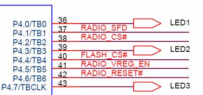
The first step is to look at the platform schematic for the epic interface board. The relevant portion for the LEDs is shown below.
The LEDS are connected to pins 65,66, and 67 of the EPIC module through 470 ohm resistors. Let’s look at the schematic for the module (http://www.cs.berkeley.edu/~prabal/projects/epic/EPIC-CORE_A_03-26-2007.pdf) The relevant portion of that shows that the LEDs connect to Port 4, pin 0, 3 and 7 on the TI MSP430 MCU.
In comparison, the schematic for the Telosb platform (http://www.tinyos.net/hardware/telos/telos-revb-2004-09-27.pdf) shows that the LEDs connect to port 5, pins 5, 6, and 7 respectively.
Pins are extremely precious on microcontrollers. They tend to use the same pin for lots of different things. Software configures the pins for the particular use. To understand the MCU we need to look at its User Guide (http://focus.ti.com/lit/ug/slau049f/slau049f.pdf)
The general architecture of the MSP430 (page 1-3) is shown below. It shows the six peripheral blocks, called ports. Each has 8 pins. The ports have different characteristics. Chapter 9 gives detail on the Digial I/O section.
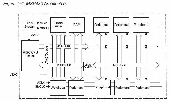
All the pins on all the ports can be either inputs or outputs. The direction is configured by setting bits in the PxDIR register, where x is the port number. For inputs, the value can be read for the PxIN reg. For outputs, the value that is driven on the output is established by writing the bit in the PxOUT register. In addition, each port has a special function beside General IO. This is selected according to bits in the PxSEL register. Ports 1 and 2 have interrupts associated with them so that external devices can interrupt the processor and cause the system to take action. Interrupts are configured and controlled through the interrupt enable (PxIE), interrupt edge select (PxIES) and Interrupt flag (PxIFG) registers. Different microcontrollers have different GIO, peripheral, and interrupt support.
Unfortunately, the Users Guide is for the whole MSP family and the different members of the family have different peripheral capabilities. That is their main distinction. In production, you pick the part that fits the need. So we need to look at the datasheet for the MSP430F1611 (http://focus.ti.com/lit/ds/symlink/msp430f1611.pdf). Page 6 has the block diagram that we really need. It is reproduced here. The following pages in the datasheet give the detail we need on the individual ports.
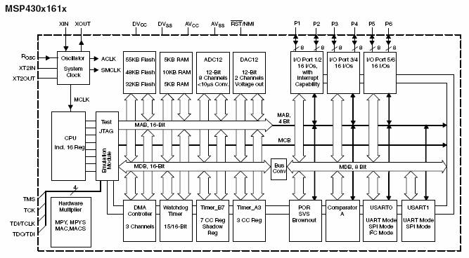
Nearly all of the hardware peripherals on the MSP430 are accessed through memory-mapped registers. The use of memory-mapped registers makes it very convenient, as you can just read and write to bits at a specific memory location. The Users guide shows how these various control registers map into the address space of the MCU so that software can access them. Setting this all up is taken care of for you. The vendor supplies include files for you C program. Note the use of P4OUT and P4DIR (P5OUT and P5DIR on Telosb).
You can find the definitions for P4DIR and P4OUT in:
/opt/msp430/msp430/include/msp430/gpio.h
-
What does the
LEDs driver do on Boot? How?
-
What if you want
to make the pin an input, what do you do?
-
What would you do
to tri-state an output pin, i.e., make it high impedence?
-
How much current
do the LEDs draw when they are on? How
does this compare with the current drawn by the MCU when it is operating?
(Hint: look at the schematic. Remember V
= IR.)
-
What would you do
to make it possible to actuate other digital outputs?
You should now know how to make pins output, set whether they are logic high or low, set them to input, and read whether they are high or low.
Power is one of the places were the digital world of Computer Science bumps against the physical analog world. In addition to consuming battery resources, there is a hard limit (described in the datasheet) on how much current can flow through an output pin. Where you need more power, you essentially need to use an external switch. Then the MCU controls the switch. This can be a relay or in many cases a FET. The EPIC Interface boards has two Digital Outs with screw terminals. The current for these comes either directly from the battery or from the 5 v booster, depending on the jumper setting. A pFET controls the current flow and the MCU controls whether the pFET is on or off.
-
You have lots of
other pins available to you on the Epic Interface Board, including MCU pins
coming off EPIC and two digital IOs with pFETs and screw terminals.
-
Pick an
interesting device to control, build a driver for it, attach it, and modify
your code to do something interesting with it.
-
What value does
the output pin need to have to close the pFET, i.e. turn the external device
on? Off?
-
Relays and Set Points - Binary outputs
The IO ports can also be configured as outputs to control and actuate external devices. The classical use of this is a relay, in which an electronic device causes a analog switch to open and close. Of course, binary outputs are also used to light LEDs and perform other functions.
One analog precaution that must be observed is the current drawn by the external device. No device should draw more than 6 mA from a pin and the total current drawn from all microcontroller outputs combined should not exceed 48 mA. This is particularly an issue when the external device is analog, such as an LED. The effective resistance should be large enough that the current draw through the output pin is within tolerance. For binary devices, current draw is seldom a problem, but attention must be paid to voltage level. The TI MSP microcontroller operates at CMOS levels, below 3.3 volts. You will notice that the LEDS in telosb are in series with a resistor to moderate the current. Even so, at 5 mA, an LED draws as much as the whole MCU!
-
Assuming that the
resistance of the LED is negligible, calculate the size of resistor that will
keep the current under 5 mA.
-
The larger the
current the brighter the LED. In fact,
your eye will perceive a rapidly blinking (20 Hz) bright LED as much brighter
than one solidly on at the same overall energy consumption.
If the LED is to consume no more than 10% of the 2 year budget, what is the total time per day that it can be on?